Multiviews
•
0 likes•4 views
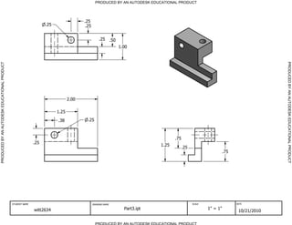
The document contains technical drawings from an Autodesk educational product. It lists dimensions for parts 3, 4, 7, 8, 10, and 11 created by student witt2634 between October 21-22, 2010. Each drawing is scaled 1 inch to 1 inch.
Report
Share
Report
Share
Download to read offline

Recommended
The ied title_block
The document contains 11 sections describing drawings produced by the student jestice7882 using an Autodesk educational product. Each section lists the drawing name, scale, and date and includes numerical coordinates. The drawings were created between October 21-29, 2010 and depict pieces or parts at a 1:1 scale.
Final pdf
The document contains technical drawings and parts lists for an assembly created by student lee2075 using Autodesk software. It includes 5 separate drawings titled Part 1 through Part 5 created on October 8, 2010 at a scale of 1 inch = 1 inch. It also includes an assembly drawing titled Assembly created on October 14, 2010 with varying scales bringing all 5 parts together. The final page lists the parts with their quantities as Part 1 (1), Part 2 (2), Part 3 (3), Part 4 (4), and Part 5 (5).
Cube Project Final
The document contains a parts list for an assembly project. It lists 5 parts with the following part numbers and quantities: Part1 (1), Part2 (4), Part3 (2), Part4 (3), Part5 (5). The parts list is preceded by documentation showing the drawings were created by a student named Tobias using Autodesk software between October 7-14, 2010.
Inventor Drawings
The document contains technical drawings from a student named depau9827 created using an Autodesk educational product. There are drawings titled "Sketching problem-3" through "Sketching problem-11" dated from October 21-25, 2010 with various scales listed. The drawings appear to be practice sketches done by the student to learn technical drawing skills.
Brian jestice inventor drawings
The document contains 11 sections describing drawings produced by the student jestice7882 using an Autodesk educational product. Each section lists the drawing name, scale, and date and includes numerical coordinates. The drawings were created between October 21-29, 2010 and depict pieces or parts at a 1:1 scale.
Cube Inventor Drawings
The document contains technical drawings and parts lists for an assembly project created by student mellado2642 using an Autodesk educational product. It includes 5 technical drawings for parts numbered c1p1 through c1p5 created on October 7, 2010 at a scale of 1 inch = 1 inch. It also includes an assembly drawing named Assemblyc1 created on October 14, 2010 at the same scale along with a parts list describing 5 parts for the assembly numbered 1 through 5 in different colors.
Puzzle Cube Presentation
The document contains technical drawings for 5 individual pieces and an assembly drawing combining the pieces. Each piece drawing is labeled with the student's name, drawing name, scale, and date. The assembly drawing brings together the 5 pieces, similarly labeled at the bottom. A parts list at the end identifies each piece and its quantity in the assembly.
Cubeprojectfinal2[1]
The document contains technical drawings and part lists produced by an Autodesk educational product. It includes 5 drawings with different colors created by student Brianne Frys between October 7-18, 2010 at a scale of 1 inch = 1 inch. A final assembly drawing brings together the individual parts in a schematic dated October 14, 2010.
Brian Jestice cross section drawings
The document contains 4 sections (A-A, B-B, C-C, D-D) of technical drawings at a scale of 1.5 inches to 1 inch. Each section depicts a cross section view and includes dimensions. Section information like scales, fillets, and rounds are provided for each view. The drawings were created using Autodesk software and include the student name, drawing name, scale, and date.
cross-section
This document contains 4 technical drawings labeled Section B-B through Section E-E. Each drawing shows the dimensions and features of a different part, including through holes, rounds, fillets, and other geometric features. The drawings are at a scale of 1/2 inch to 1 inch and were created by an Autodesk educational product. They include the student name, drawing name, scale, and date.
Cube project
The document contains technical drawings and part lists for an assembly created by a student named swenson1906 using Autodesk educational software. It includes individual drawings scaled at 1"=1" for parts in blue, light green, pink, yellow, and purple created between October 6-7, 2010. These parts are then assembled together in a final drawing labeled 1-Assembly.iam with varying scales and dated October 14, 2010 along with a parts list detailing the parts and their quantities.
Bran jestice cube
The document is a parts list for an assembly project. It lists 5 parts with their corresponding part numbers and quantities. The parts list is preceded by multiple pages showing the technical drawings for the individual parts, including dimensions. The drawings were created by a student named jestice7882 using Autodesk software between October 6-14, 2010.
Helling Portfolio
This document contains an interior design portfolio belonging to Marissa Helling from the University of North Texas. It includes floor plans and furniture layouts for various commercial and institutional projects designed using software like AutoCAD, SketchUp, and InDesign. The projects showcase her skills in space planning, furniture specification, and conceptual design for clients in sectors like corporate offices, retail, education, and restaurants.
8.Views.pdf
The document discusses SQL views and provides examples of creating views. It defines a view as a query expression that computes and stores results but does not persist them on disk. Views allow restricting access to only specific columns of a table. Examples shown create views to list faculty without salaries, biology course sections, and total salaries by department.
CASTING DEFECTS ANALYSIS OF SWASH PLATE (PVB10 YOKE) USING SIMULATION
This document discusses using casting simulation software to analyze and reduce defects in castings of a swash plate component (PVB10 Yoke). It conducted four trials over multiple months: the first using traditional methods resulted in 42.5% rejection due to shrinkage porosity and other defects. The second trial placed a core but rejection remained high. The third trial used casting simulation software which identified riser size as the cause of shrinkage porosity. The fourth trial increased riser size, resulting in only 5% rejection. Using simulation enabled identifying the root cause of defects and reducing the rejection rate from 42.5% to 5% for the swash plate casting.
Final title anthony_l_brian_j_cj_p_2[1]
The document contains technical drawings and specifications for various mechanical parts produced by Autodesk educational software, including a linkage arm, wheel, vehicle body, smokestack, and other unlabeled parts. The drawings include dimensions, tolerances, notes, and section and detail views labeled with scales. Student names and dates are provided in the title blocks.
TrainCarMultiviews
The document contains technical drawings for parts of a model car created by a student named witt2634 using Autodesk software. The drawings include dimensions and notes for a base, two sides, two side connectors, and four wheels. A final assembly drawing shows how to assemble the seven listed parts into a complete model car.
Productivity Enhancement of Clipping Machine
This document summarizes a project to increase productivity of a clipping machine at a pencil manufacturing plant. The researchers designed and installed a hopper and feeder bowl system to automate the manual placement of clips and barrels. Through analysis of production data using quality tools like why-why analysis and fishbone diagrams, they identified inconsistent manual placement as the root cause of rejections. Their automated design calculations showed the hopper could hold 1481 barrels, increasing throughput. The new system aims to reduce labor costs, improve quality, and increase productivity by fully automating the clipping process.
AutoCAD Design Project
The document contains bills of materials and bolt lists for various structural components of a final engineering project produced by Michael Masi and Vincent Vincelli. It includes 13 sections for different components like the pier and stub, crain rail, angle joist, etc. Each section contains detailed lists of the materials and fasteners needed with identification numbers, descriptions, lengths and quantities.
Patrick kiracollaboration
The document is a Skype chat log between members of a group project team. They discuss dividing up tasks like creating a compilation of documents, drawings, and a prototype. They also mention creating a Gantt chart and norms sheet. They share ideas for their ball pit design project and send sketches back and forth. They discuss plans over spring break and completing research assignments.
MiniGolfTeamNorms
The team norms document outlines the code of conduct, communication methods, file management structure, decision making process, and task assignments for the team. It states that members must respect each other's ideas and be open to new ones, with no offensive language or turning down ideas allowed. It also specifies that email is the primary communication method, files should be shared and revised as soon as possible, photos will be emailed for design decisions, and compromise is required to deal with differences of opinion. It assigns responsibilities for compiling documents, drawings, the prototype, and collaboration documents. Each member must read and agree to the norms.
EcoBrief
The design brief is for a client company called B.A.P. Incorporated to design a boat made from 100% recycled materials that can transport people on a river to access new food sources. The target consumers are people who use the river for transportation to gather food but cannot make their own boat. The designers are Bobby McDonald, Patrick Witt, and Alexander Huff. The boat will be made from wood pallets and recycled water bottles and must be able to carry additional weight like food.
EcoPresentation
This document discusses several environmental issues and proposes an eco-challenge to address them. It notes that water bottles do not decompose for thousands of years, 10% of plastic produced ends up in the oceans, and 2/3 of pallets are used once and thrown out. The eco-challenge proposes creating boats from recycled materials like pallets and water bottles to provide affordable transportation for fishing jobs, helping address poverty while reducing waste.
EcoChallenge
B.A.P. Incorporated has tasked designers Bobby McDonald, Patrick Witt, and Alexander Huff with developing a boat made entirely from recycled materials to transport people on rivers to access new food sources. The boat will be constructed from wood pallets and recycled water bottles, and must be able to carry additional weight like food while using only recycled materials.
Reverse Engineering Project
The document summarizes the parts of an indicator fixture device. It includes 13 numbered parts such as a back board, indicator outlets, screws of various sizes, a handle, horizontal and vertical panels, a base, and electrical connection components. Each part lists relevant dimensions, materials, functions, and general notes. The purpose is to provide a detailed breakdown of all components that make up the indicator fixture.
DecisionMatrix
A document compares three ideas based on complexity, build time, and safety criteria. Idea 1 scores highest with 9 points total, followed by Idea 2 with 6 points, and Idea 3 with 8 points.
Train Research
The document discusses features the author likes about various train cars and locomotives. These include wheels spaced far apart for balance, rounded fronts and backs for aerodynamics, awnings over sides for covered transfers in poor weather, guardrails to prevent falling off, close spacing to improve transfers, wheels without spokes to support weight, an area between wheels that dips for power and balance, a lookout on cabooses for perspective, pulling capacity for long distances with weight, rounded bumpers to reduce damage, spaced wheels with only two at each end for cornering, a raised middle section of the overhead for efficiency, wheels on axes for precise turning, and a small size compared to others for lighter weight and faster travel.
TrainCarResearch
The document discusses features the author likes about various train cars and locomotives. The author likes how some cars have wheels spaced far apart for balance, rounded tops and fronts/backs for aerodynamics, awnings over sides for covered transfers, guardrails to prevent falling, close spacing to improve transfers, dipping areas between wheels for balance and power production, lookouts on cabooses for perspective, pulling power to transport many cars long distances, bumpers to reduce damage from crashes, spaced wheels for cornering, raised midsections for efficiency, axled wheels for precise turning, and smaller size compared to other cars for lighter weight and faster travel.
TrainEngineInventorDrawings
The document contains technical drawings and part lists for a model train assembly project. It includes drawings for 5 different train parts - the train body, cow catcher, linkage arm, and wheel - along with a parts list identifying 9 total parts needed for assembly. Each drawing is labeled with the part name, student name, scale, and date.
More Related Content
Similar to Multiviews
Cubeprojectfinal2[1]
The document contains technical drawings and part lists produced by an Autodesk educational product. It includes 5 drawings with different colors created by student Brianne Frys between October 7-18, 2010 at a scale of 1 inch = 1 inch. A final assembly drawing brings together the individual parts in a schematic dated October 14, 2010.
Brian Jestice cross section drawings
The document contains 4 sections (A-A, B-B, C-C, D-D) of technical drawings at a scale of 1.5 inches to 1 inch. Each section depicts a cross section view and includes dimensions. Section information like scales, fillets, and rounds are provided for each view. The drawings were created using Autodesk software and include the student name, drawing name, scale, and date.
cross-section
This document contains 4 technical drawings labeled Section B-B through Section E-E. Each drawing shows the dimensions and features of a different part, including through holes, rounds, fillets, and other geometric features. The drawings are at a scale of 1/2 inch to 1 inch and were created by an Autodesk educational product. They include the student name, drawing name, scale, and date.
Cube project
The document contains technical drawings and part lists for an assembly created by a student named swenson1906 using Autodesk educational software. It includes individual drawings scaled at 1"=1" for parts in blue, light green, pink, yellow, and purple created between October 6-7, 2010. These parts are then assembled together in a final drawing labeled 1-Assembly.iam with varying scales and dated October 14, 2010 along with a parts list detailing the parts and their quantities.
Bran jestice cube
The document is a parts list for an assembly project. It lists 5 parts with their corresponding part numbers and quantities. The parts list is preceded by multiple pages showing the technical drawings for the individual parts, including dimensions. The drawings were created by a student named jestice7882 using Autodesk software between October 6-14, 2010.
Helling Portfolio
This document contains an interior design portfolio belonging to Marissa Helling from the University of North Texas. It includes floor plans and furniture layouts for various commercial and institutional projects designed using software like AutoCAD, SketchUp, and InDesign. The projects showcase her skills in space planning, furniture specification, and conceptual design for clients in sectors like corporate offices, retail, education, and restaurants.
8.Views.pdf
The document discusses SQL views and provides examples of creating views. It defines a view as a query expression that computes and stores results but does not persist them on disk. Views allow restricting access to only specific columns of a table. Examples shown create views to list faculty without salaries, biology course sections, and total salaries by department.
CASTING DEFECTS ANALYSIS OF SWASH PLATE (PVB10 YOKE) USING SIMULATION
This document discusses using casting simulation software to analyze and reduce defects in castings of a swash plate component (PVB10 Yoke). It conducted four trials over multiple months: the first using traditional methods resulted in 42.5% rejection due to shrinkage porosity and other defects. The second trial placed a core but rejection remained high. The third trial used casting simulation software which identified riser size as the cause of shrinkage porosity. The fourth trial increased riser size, resulting in only 5% rejection. Using simulation enabled identifying the root cause of defects and reducing the rejection rate from 42.5% to 5% for the swash plate casting.
Final title anthony_l_brian_j_cj_p_2[1]
The document contains technical drawings and specifications for various mechanical parts produced by Autodesk educational software, including a linkage arm, wheel, vehicle body, smokestack, and other unlabeled parts. The drawings include dimensions, tolerances, notes, and section and detail views labeled with scales. Student names and dates are provided in the title blocks.
TrainCarMultiviews
The document contains technical drawings for parts of a model car created by a student named witt2634 using Autodesk software. The drawings include dimensions and notes for a base, two sides, two side connectors, and four wheels. A final assembly drawing shows how to assemble the seven listed parts into a complete model car.
Productivity Enhancement of Clipping Machine
This document summarizes a project to increase productivity of a clipping machine at a pencil manufacturing plant. The researchers designed and installed a hopper and feeder bowl system to automate the manual placement of clips and barrels. Through analysis of production data using quality tools like why-why analysis and fishbone diagrams, they identified inconsistent manual placement as the root cause of rejections. Their automated design calculations showed the hopper could hold 1481 barrels, increasing throughput. The new system aims to reduce labor costs, improve quality, and increase productivity by fully automating the clipping process.
AutoCAD Design Project
The document contains bills of materials and bolt lists for various structural components of a final engineering project produced by Michael Masi and Vincent Vincelli. It includes 13 sections for different components like the pier and stub, crain rail, angle joist, etc. Each section contains detailed lists of the materials and fasteners needed with identification numbers, descriptions, lengths and quantities.
Similar to Multiviews (12)
CASTING DEFECTS ANALYSIS OF SWASH PLATE (PVB10 YOKE) USING SIMULATION
CASTING DEFECTS ANALYSIS OF SWASH PLATE (PVB10 YOKE) USING SIMULATION
More from P1666
Patrick kiracollaboration
The document is a Skype chat log between members of a group project team. They discuss dividing up tasks like creating a compilation of documents, drawings, and a prototype. They also mention creating a Gantt chart and norms sheet. They share ideas for their ball pit design project and send sketches back and forth. They discuss plans over spring break and completing research assignments.
MiniGolfTeamNorms
The team norms document outlines the code of conduct, communication methods, file management structure, decision making process, and task assignments for the team. It states that members must respect each other's ideas and be open to new ones, with no offensive language or turning down ideas allowed. It also specifies that email is the primary communication method, files should be shared and revised as soon as possible, photos will be emailed for design decisions, and compromise is required to deal with differences of opinion. It assigns responsibilities for compiling documents, drawings, the prototype, and collaboration documents. Each member must read and agree to the norms.
EcoBrief
The design brief is for a client company called B.A.P. Incorporated to design a boat made from 100% recycled materials that can transport people on a river to access new food sources. The target consumers are people who use the river for transportation to gather food but cannot make their own boat. The designers are Bobby McDonald, Patrick Witt, and Alexander Huff. The boat will be made from wood pallets and recycled water bottles and must be able to carry additional weight like food.
EcoPresentation
This document discusses several environmental issues and proposes an eco-challenge to address them. It notes that water bottles do not decompose for thousands of years, 10% of plastic produced ends up in the oceans, and 2/3 of pallets are used once and thrown out. The eco-challenge proposes creating boats from recycled materials like pallets and water bottles to provide affordable transportation for fishing jobs, helping address poverty while reducing waste.
EcoChallenge
B.A.P. Incorporated has tasked designers Bobby McDonald, Patrick Witt, and Alexander Huff with developing a boat made entirely from recycled materials to transport people on rivers to access new food sources. The boat will be constructed from wood pallets and recycled water bottles, and must be able to carry additional weight like food while using only recycled materials.
Reverse Engineering Project
The document summarizes the parts of an indicator fixture device. It includes 13 numbered parts such as a back board, indicator outlets, screws of various sizes, a handle, horizontal and vertical panels, a base, and electrical connection components. Each part lists relevant dimensions, materials, functions, and general notes. The purpose is to provide a detailed breakdown of all components that make up the indicator fixture.
DecisionMatrix
A document compares three ideas based on complexity, build time, and safety criteria. Idea 1 scores highest with 9 points total, followed by Idea 2 with 6 points, and Idea 3 with 8 points.
Train Research
The document discusses features the author likes about various train cars and locomotives. These include wheels spaced far apart for balance, rounded fronts and backs for aerodynamics, awnings over sides for covered transfers in poor weather, guardrails to prevent falling off, close spacing to improve transfers, wheels without spokes to support weight, an area between wheels that dips for power and balance, a lookout on cabooses for perspective, pulling capacity for long distances with weight, rounded bumpers to reduce damage, spaced wheels with only two at each end for cornering, a raised middle section of the overhead for efficiency, wheels on axes for precise turning, and a small size compared to others for lighter weight and faster travel.
TrainCarResearch
The document discusses features the author likes about various train cars and locomotives. The author likes how some cars have wheels spaced far apart for balance, rounded tops and fronts/backs for aerodynamics, awnings over sides for covered transfers, guardrails to prevent falling, close spacing to improve transfers, dipping areas between wheels for balance and power production, lookouts on cabooses for perspective, pulling power to transport many cars long distances, bumpers to reduce damage from crashes, spaced wheels for cornering, raised midsections for efficiency, axled wheels for precise turning, and smaller size compared to other cars for lighter weight and faster travel.
TrainEngineInventorDrawings
The document contains technical drawings and part lists for a model train assembly project. It includes drawings for 5 different train parts - the train body, cow catcher, linkage arm, and wheel - along with a parts list identifying 9 total parts needed for assembly. Each drawing is labeled with the part name, student name, scale, and date.
CrossSectionDrawings
The document contains technical drawings of two mechanical parts - a bracket and coupling. The drawings include dimensional measurements and section views with notes on fillets and scales. Additional information provided on the drawings includes the student name who produced them, the names of the parts, and the date.
AuxillaryDrawing
This document appears to be a technical drawing created by an Autodesk educational product. The drawing includes dimensions for various lines and shapes, including rectangles and circles. At the bottom it lists the student name, drawing name, scale, and date the drawing was produced.
Inventor Tutorial
This document describes various 3D modeling features available in CAD software and provides instructions for exercises to practice using these features. It includes descriptions and examples of midplane extrusions, intersect extrusions, tapered extrusions, revolves, holes, lofts, circular patterns, and rectangular patterns. Students are asked to complete exercises using these features in CAD files provided and export images of the results.
Inventor Practice Problems
The document appears to be a collection of technical drawings produced by a student named witt2634 using an Autodesk educational software. There are 8 pages of drawings labeled Part3 through Part8, each with technical drawings consisting of lines and measurements. Each page contains the student name, drawing name, scale, and date in the header.
Inventor Drawing Assignment
The document contains technical drawings produced by an Autodesk educational product. Each page contains information about the student name, drawing name, scale, and date. Dimensions ranging from 0.25 to 2.75 are listed on each page. There are multiple pages showing different drawings by the same student on various dates.
Multiviews
The document contains technical drawings produced by an Autodesk educational product. Each page contains information about the student name, drawing name, scale, and date. Dimensions ranging from 0.25 to 2.75 are listed on each page. There are multiple pages showing different drawings by the same student on various dates.
Puzzle Cube Project
The document contains technical drawings and specifications for 5 different colored pieces - black, blue, green, purple, and red - designed by Patrick Witt on 10.19.10. Each drawing lists the dimensions of the piece in inches, and there is a corresponding parts list that assigns a part number and quantity to each of the 5 pieces.
History of the Calculator
The abacus, one of the earliest calculators dating back 2500 years to Asia Minor, was based on the human hand and used beads to perform calculations. In the 17th century, Wilhelm Schickard created a machine that could add and subtract 6-digit numbers using a rotating wheel. Gottfried Leibniz then developed the first calculator that could perform all four basic arithmetic functions using a stepped drum mechanism. Throughout the 19th and early 20th centuries, various inventors developed new calculating machines with full keyboards and printing capabilities to help with calculations in businesses. Konrad Zuse then created the first binary computer in 1936 using metal plates for memory instead of chips. This led to the development of the microprocessor and modern calcul
More from P1666 (20)
Recently uploaded
Pollock and Snow "DEIA in the Scholarly Landscape, Session One: Setting Expec...
Pollock and Snow "DEIA in the Scholarly Landscape, Session One: Setting Expec...National Information Standards Organization (NISO)
This presentation was provided by Steph Pollock of The American Psychological Association’s Journals Program, and Damita Snow, of The American Society of Civil Engineers (ASCE), for the initial session of NISO's 2024 Training Series "DEIA in the Scholarly Landscape." Session One: 'Setting Expectations: a DEIA Primer,' was held June 6, 2024.Assessment and Planning in Educational technology.pptx
In an education system, it is understood that assessment is only for the students, but on the other hand, the Assessment of teachers is also an important aspect of the education system that ensures teachers are providing high-quality instruction to students. The assessment process can be used to provide feedback and support for professional development, to inform decisions about teacher retention or promotion, or to evaluate teacher effectiveness for accountability purposes.
Advanced Java[Extra Concepts, Not Difficult].docx
This is part 2 of my Java Learning Journey. This contains Hashing, ArrayList, LinkedList, Date and Time Classes, Calendar Class and more.
The History of Stoke Newington Street Names
Presented at the Stoke Newington Literary Festival on 9th June 2024
www.StokeNewingtonHistory.com
DRUGS AND ITS classification slide share
Any substance (other than food) that is used to prevent, diagnose, treat, or relieve symptoms of a
disease or abnormal condition
Natural birth techniques - Mrs.Akanksha Trivedi Rama University
Natural birth techniques - Mrs.Akanksha Trivedi Rama UniversityAkanksha trivedi rama nursing college kanpur.
Natural birth techniques are various type such as/ water birth , alexender method, hypnosis, bradley method, lamaze method etcHindi varnamala | hindi alphabet PPT.pdf
हिंदी वर्णमाला पीपीटी, hindi alphabet PPT presentation, hindi varnamala PPT, Hindi Varnamala pdf, हिंदी स्वर, हिंदी व्यंजन, sikhiye hindi varnmala, dr. mulla adam ali, hindi language and literature, hindi alphabet with drawing, hindi alphabet pdf, hindi varnamala for childrens, hindi language, hindi varnamala practice for kids, https://www.drmullaadamali.com
How to Build a Module in Odoo 17 Using the Scaffold Method
Odoo provides an option for creating a module by using a single line command. By using this command the user can make a whole structure of a module. It is very easy for a beginner to make a module. There is no need to make each file manually. This slide will show how to create a module using the scaffold method.
Exploiting Artificial Intelligence for Empowering Researchers and Faculty, In...
Exploiting Artificial Intelligence for Empowering Researchers and Faculty, In...Dr. Vinod Kumar Kanvaria
Exploiting Artificial Intelligence for Empowering Researchers and Faculty,
International FDP on Fundamentals of Research in Social Sciences
at Integral University, Lucknow, 06.06.2024
By Dr. Vinod Kumar Kanvariaবাংলাদেশ অর্থনৈতিক সমীক্ষা (Economic Review) ২০২৪ UJS App.pdf
বাংলাদেশের অর্থনৈতিক সমীক্ষা ২০২৪ [Bangladesh Economic Review 2024 Bangla.pdf] কম্পিউটার , ট্যাব ও স্মার্ট ফোন ভার্সন সহ সম্পূর্ণ বাংলা ই-বুক বা pdf বই " সুচিপত্র ...বুকমার্ক মেনু 🔖 ও হাইপার লিংক মেনু 📝👆 যুক্ত ..
আমাদের সবার জন্য খুব খুব গুরুত্বপূর্ণ একটি বই ..বিসিএস, ব্যাংক, ইউনিভার্সিটি ভর্তি ও যে কোন প্রতিযোগিতা মূলক পরীক্ষার জন্য এর খুব ইম্পরট্যান্ট একটি বিষয় ...তাছাড়া বাংলাদেশের সাম্প্রতিক যে কোন ডাটা বা তথ্য এই বইতে পাবেন ...
তাই একজন নাগরিক হিসাবে এই তথ্য গুলো আপনার জানা প্রয়োজন ...।
বিসিএস ও ব্যাংক এর লিখিত পরীক্ষা ...+এছাড়া মাধ্যমিক ও উচ্চমাধ্যমিকের স্টুডেন্টদের জন্য অনেক কাজে আসবে ...
Top five deadliest dog breeds in America
Thinking of getting a dog? Be aware that breeds like Pit Bulls, Rottweilers, and German Shepherds can be loyal and dangerous. Proper training and socialization are crucial to preventing aggressive behaviors. Ensure safety by understanding their needs and always supervising interactions. Stay safe, and enjoy your furry friends!
Recently uploaded (20)
Pollock and Snow "DEIA in the Scholarly Landscape, Session One: Setting Expec...
Pollock and Snow "DEIA in the Scholarly Landscape, Session One: Setting Expec...
Pride Month Slides 2024 David Douglas School District
Pride Month Slides 2024 David Douglas School District
Assessment and Planning in Educational technology.pptx
Assessment and Planning in Educational technology.pptx
Digital Artefact 1 - Tiny Home Environmental Design
Digital Artefact 1 - Tiny Home Environmental Design
Film vocab for eal 3 students: Australia the movie
Film vocab for eal 3 students: Australia the movie
Natural birth techniques - Mrs.Akanksha Trivedi Rama University
Natural birth techniques - Mrs.Akanksha Trivedi Rama University
How to Build a Module in Odoo 17 Using the Scaffold Method
How to Build a Module in Odoo 17 Using the Scaffold Method
Liberal Approach to the Study of Indian Politics.pdf
Liberal Approach to the Study of Indian Politics.pdf
Exploiting Artificial Intelligence for Empowering Researchers and Faculty, In...
Exploiting Artificial Intelligence for Empowering Researchers and Faculty, In...
বাংলাদেশ অর্থনৈতিক সমীক্ষা (Economic Review) ২০২৪ UJS App.pdf
বাংলাদেশ অর্থনৈতিক সমীক্ষা (Economic Review) ২০২৪ UJS App.pdf
Multiviews
- 1. PRODUCED BY AN AUTODESK EDUCATIONAL PRODUCT PRODUCED BY AN AUTODESK EDUCATIONAL PRODUCTPRODUCEDBYANAUTODESKEDUCATIONALPRODUCT PRODUCEDBYANAUTODESKEDUCATIONALPRODUCT STUDENT NAME DRAWING NAME SCALE DATE witt2634 Part3.ipt 1" = 1" 10/21/2010 .75 .25 .25 1.00 .50 .25 .75 1.25 .25 .38 .25 1.25 2.00 .25 .25
- 2. PRODUCED BY AN AUTODESK EDUCATIONAL PRODUCT PRODUCED BY AN AUTODESK EDUCATIONAL PRODUCTPRODUCEDBYANAUTODESKEDUCATIONALPRODUCT PRODUCEDBYANAUTODESKEDUCATIONALPRODUCT STUDENT NAME DRAWING NAME SCALE DATE witt2634 Part4.ipt 1" = 1" 10/21/2010 .50 .75 2.25 .25 .50 1.50 R.50 1.00 .75 1.25 .25 1.00 1.50 .25 .25
- 3. PRODUCED BY AN AUTODESK EDUCATIONAL PRODUCT PRODUCED BY AN AUTODESK EDUCATIONAL PRODUCTPRODUCEDBYANAUTODESKEDUCATIONALPRODUCT PRODUCEDBYANAUTODESKEDUCATIONALPRODUCT STUDENT NAME DRAWING NAME SCALE DATE witt2634 Part7.ipt 1" = 1" 10/22/2010 .50 1.00 .25 1.75 1.00 1.50 R.25 R.64 1.25 2.75 .50 .50 R.75 .75 .75
- 4. PRODUCED BY AN AUTODESK EDUCATIONAL PRODUCT PRODUCED BY AN AUTODESK EDUCATIONAL PRODUCTPRODUCEDBYANAUTODESKEDUCATIONALPRODUCT PRODUCEDBYANAUTODESKEDUCATIONALPRODUCT STUDENT NAME DRAWING NAME SCALE DATE witt2634 Part8.ipt 1" = 1" 10/22/2010 1.00 .50 2.75 1.00 1.00 1.50 2.00 1.00 .50 1.00 .50 1.00 R.25 .50 R.50
- 5. PRODUCED BY AN AUTODESK EDUCATIONAL PRODUCT PRODUCED BY AN AUTODESK EDUCATIONAL PRODUCTPRODUCEDBYANAUTODESKEDUCATIONALPRODUCT PRODUCEDBYANAUTODESKEDUCATIONALPRODUCT STUDENT NAME DRAWING NAME SCALE DATE witt2634 Part10.ipt 1" = 1" 10/22/2010 .50 1.00 .50 1.00 1.00 2.75 .50 1.75 R.50 .50 1.00.50
- 6. PRODUCED BY AN AUTODESK EDUCATIONAL PRODUCT PRODUCED BY AN AUTODESK EDUCATIONAL PRODUCTPRODUCEDBYANAUTODESKEDUCATIONALPRODUCT PRODUCEDBYANAUTODESKEDUCATIONALPRODUCT STUDENT NAME DRAWING NAME SCALE DATE witt2634 Part11.ipt 1" = 1" 10/22/2010 1.00 2.00 1.00 .50.50 1.25 1.00 .50